

RELATED POSTS
RELATED PRODUCTS
MORE INFO
Deploying PTP over PRP
Net.Time φ is compatible with the PTP Utility Profile (IEC 61850-9-3) and PRP (IEC 62439-3). These protocols are great when they work together offering the failsafe, accurate timing over required in digital substation applications.
BARCELONA 01.05.23
Parallel Redundancy Protocol
The Parallel Redundancy Protocol (PRP) provides failsafe operation in a LAN by duplicating the transmission media so that they work in parallel. Every piece of information is transmitted twice over mutually isolated networks (LAN A and LAN B). If one of the replicas is lost, it is very likely that the the information is still received through the alternative channel. In normal operation conditions, frames are received twice and Doubly Attached Nodes (DANs) implement a duplication detection algorithm designed to drop most duplicated frames before they are processed by higher protocol layers.
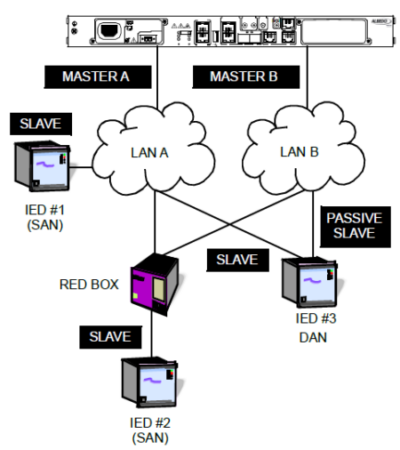
Fig 1. PRP provides redundant communications to IED #2 and #3. IED#1 is sensitive to network faults.
Singly Attached Nodes
The PRP standard is flexible enough to accept interoperability with nodes connected to only LAN A or LAN B. These are called Singly Attached Nodes (SANs). There are not strict requirements for LAN A and LAN B. These are typically bridged Ethernet networks designed so that a failure event in one of them does not affect to the second network.
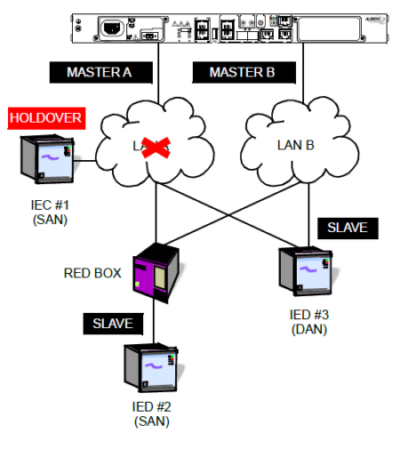
Fig 2. IED #2 and #3 keep their normal operating conditions when LAN A stops working but IEC #1 loses its connection to the PTP grandmaster and it goes to holdover.
Timing distribution
Timing distribution in PRP networks is a challenge because timing information is collected from two channels with two delay paths. This fact makes delay compensation unfeasible. At some point, the slave could be applying a compensation derived for LAN A in a Sync packet received in Port B. The solution to this issue is addressed in IEC 61850-9-3, the PTP Utility Profile: A DAN operating in PTP slave mode will keep only one of the ports in SLAVE state while the other remains in PASSIVE SLAVE mode. PASSIVE SLAVE and SLAVE ports are similar but PASSIVE SLAVE ports do not discipline the oscillator unless a fault is detected in the SLAVE port. PASSIVE SLAVE port becomes a regular SLAVE port. With this procedure, consistency between PTP synchronization (Sync message flow) and delay compensation (Peer Delay Request / Response flows) procedures is guaranteed.

Fig 3. ALBEDO Net.Time supports PTP and NTP over PRP.