Net.Time configuration
This note aims to guide users through the configuration of Net.Time. Whether setting it up as a Grandmaster, Boundary Clock, or NTP Server, the document covers essential steps to optimize its performance and and align with specific requirements.
MIAMI 10.12.2024
Net.Time is ALBEDO’s cutting-edge timing solution designed to ensure precision and reliability in critical infrastructure applications. With support for a wide range of synchronization protocols such as PTP, NTP, IRIG-B, and C37.118, Net.Time is ideal for industries requiring accurate timing, including utilities, telecom, transportation, and defense. Its robust hardware, featuring advanced GNSS capabilities, high-stability oscillators, and redundant power supplies, ensures top performance in even the most demanding environments.

Fig 1. Net.Time network clock.
This application note aims to guide users through the configuration process of Net.Time. Whether setting it up as a Grandmaster Clock, Boundary Clock, or NTP Server, the document covers essential steps to optimize its performance and align with specific network requirements. Practical tips, best practices, and troubleshooting advice are included to help users make the most of this versatile synchronization appliance. By the end of this guide, you’ll have a clear understanding of how to configure Net.Time for seamless integration into your infrastructure, ensuring compliance with industry standards and achieving unparalleled time synchronization accuracy.
Initial Configuration: Console Connection
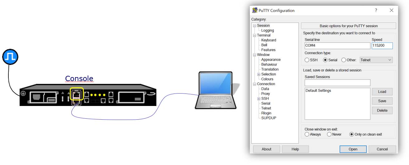
Fig 2. Specify the destination you want to connect.
- Connect the Laptop: Use a USB-to-RJ45 console cable to connect your laptop to the Net.Time device.
- Install Communication Software: Ensure you have a terminal emulator, such as PuTTY, installed on your laptop.
- Identify the USB Port: Open your device manager to determine the correct USB port (e.g., COM4).
- Set Baud Rate: Configure the connection with a speed of 115,200 bps for proper communication.
- Select Connection Type: Choose Serial as the connection type in the communication software.
For establishing Communication via Console you have to wait a black console window will appear then enter the credentials then press <Enter> to activate the prompt:
- Login: admin
- Password: admin
You can now access the Command Line Interface (CLI) and use the commands listed in the Provisioning Guide to configure and manage Net.Time.
Switching to the Web GUI
The web server will facilitate your work if you are not confident with the CLI and you will be able to manage the configuration, the status of the timing input, output ports including Ethernet and the timing protocols. You can configure and spot the changes.
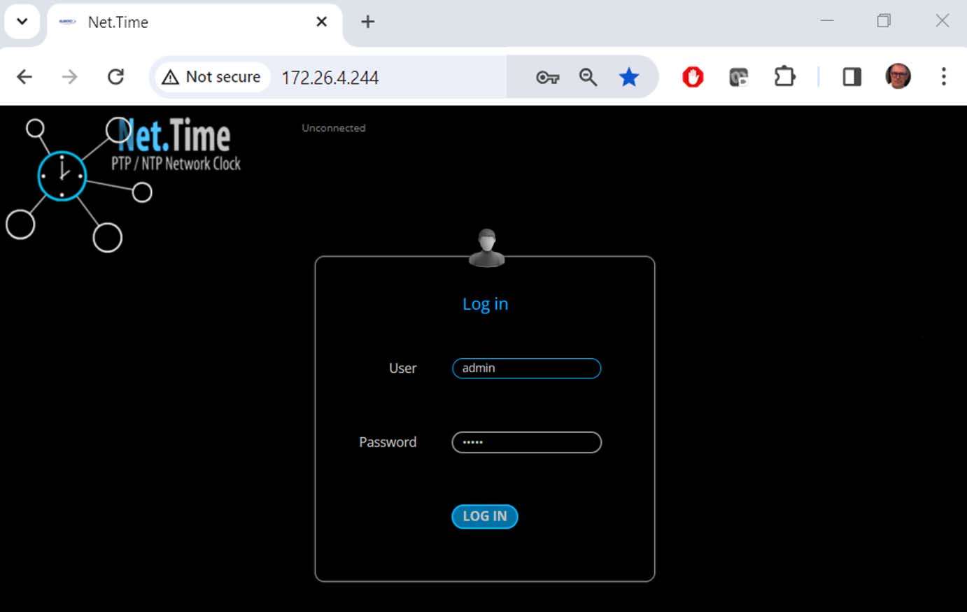
Fig 3. The web server.
While the CLI provides full control, managing Net.Time is more convenient using the web GUI. This setup offers a more user-friendly interface for managing Net.Time. To access it first connect the Management Port to your network and then ensure the port is properly configured as described in the User Manual and finally open a web browser and navigate to the device’s IP address to access the intuitive Web GUI.
Now Accessing the Application via Web Browser using your laptop and enter the IP address of the Net.Time device in the address bar. It ca be HTTP or HTTPS protocol, depending on how the device is configured. You need now Login and define User Roles. The application will prompt you to enter login credentials to set up the username and password. Net.Time supports three user roles with different levels of access:
- Administrators: Full control over configuration and management.
- Controllers: Limited to specific operational tasks.
- Viewers: Read-only access to monitor system status and performance.
This role-based system ensures secure and organized access to the application.
Mapping Interfaces to Ports
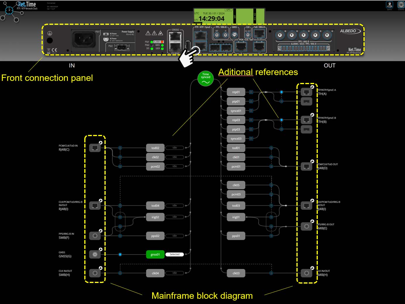
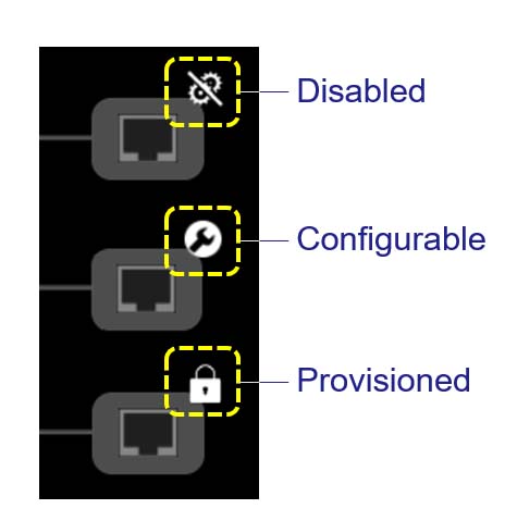
Mapping is the process of assigning specific functions or signals to the input and output ports of the Net.Time device. It ensures flexibility and adaptability by allowing users to configure ports based on their synchronization requirements. There are serveral options. We have the Output Ports that define which signal is provided on each output port (e.g., NTP, SyncE, PTP) and the Input Ports that specify which timing reference is accepted on each input port. Interface Selection is required to map interface using two types of selection controls:

Fig 5. Mapping Interfaces to Ports.
(a) Square Checkboxes: Allow the configuration of multiple protocols simultaneously on the same port. Example: A single port can support both NTP and SyncE protocols (see 1).
(b) Round Radio Buttons: Indicate that the selection is exclusive for a path or protocol. Example: A port can be configured to support only one type of electrical interface at a time (see 2).
This intuitive mapping system provides flexibility while ensuring precise control over the assignment of signals and protocols to ports.
Grandmaster
In Grandmaster PS, Net.Time functions as a multi-port PTP Grandmaster or an NTP server, delivering precise timing to devices across the network. The implementation adheres to industry standards to ensure accuracy and reliability:
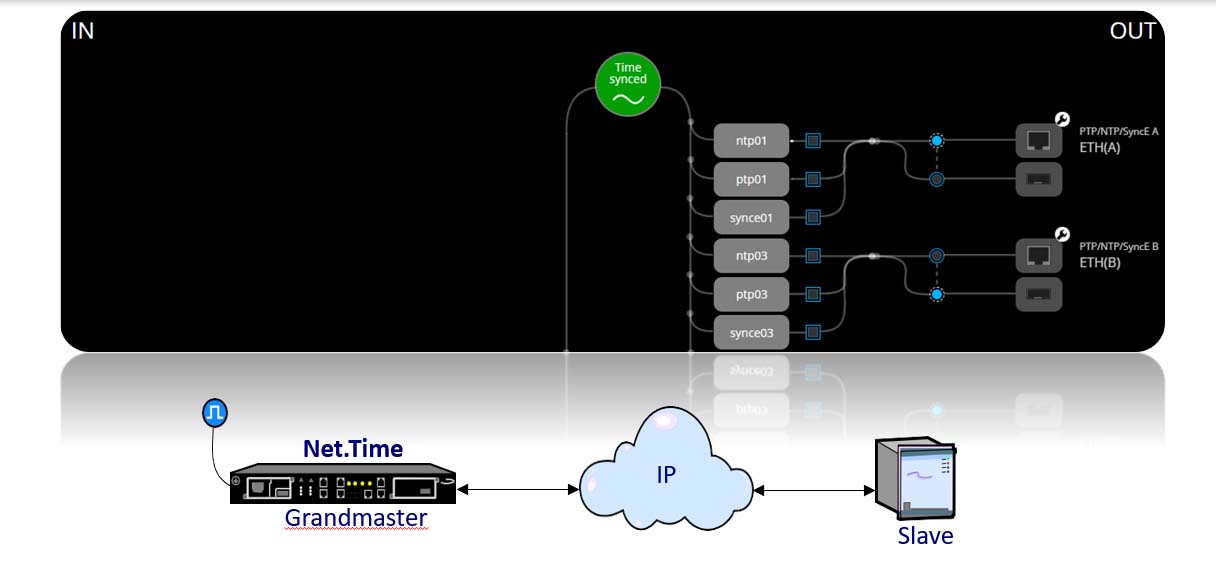
Fig 8. Net.Time Grandmaster network clock.
- PTP (IEEE 1588):
- The functionality aligns with the block diagram of an IEEE 1588 Ordinary Clock, ensuring precise synchronization.
- To maintain its role as a Grandmaster, the clock is configured to prevent the engine from ever transitioning into the slave role, using procedures dependent on the selected profile.
- NTP (RFC 1305 & RFC 5905):
- Supports both NTPv3 and NTPv4 standards.
- Operates as an authoritative time source, providing synchronization to all configured clients.
This mode ensures that Net.Time serves as a robust and reliable synchronization source, maintaining its Grandmaster status in PTP networks and operating seamlessly as an NTP server.
PRP Grandmaster
In PRP Grandmaster mode, Net.Time assigns Ethernet ports to PRP ports and maps the appropriate PTP/NTP packet services, such as PTP ISO/IEC 61850-9-3 Grandmaster and NTP server. Configuring a different packet service will release the Ethernet ports assigned to PRP. If the PTP Grandmaster service is mapped over PRP, these ports will be reassigned to standard ETH ports, and the PRP virtual ports will be removed from the port list. This mode ensures high availability and redundancy by supporting PRP, providing path redundancy for PTP and NTP services.
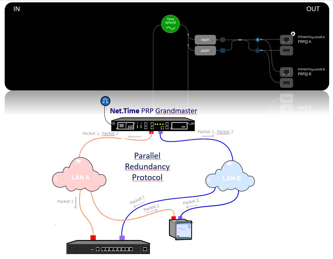
Fig 9. Net.Time PRP Grandmaster network clock.
Protocol Translator
In Protocol Translator mode, Ethernet ports are configured to support different protocols for input and output. For example:
- Ethernet port A might be assigned to PTP
- Ethernet port B might be assigned to NTP
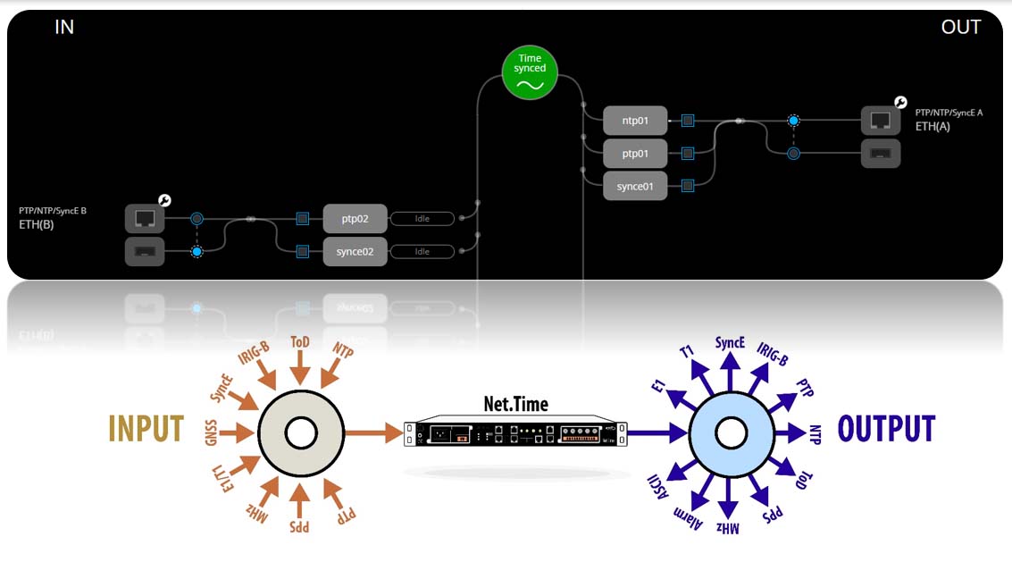
Fig 10. Net.Time Protocol Traslator network clock.
This mode facilitates the translation and transfer of different timing protocols between input and output, ensuring flexibility and enabling network resilience. A backup protocol can be automatically switched in case of failure of the primary reference. These modes provide powerful features for protocol translation, redundancy, and flexible configuration to meet diverse network synchronization needs.
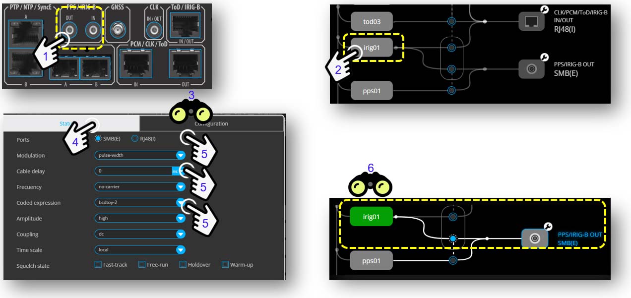
Fig 11. Configuration of an IRIG-B output.
About Net.Time
Net.Time is a PTP/NTP over PRP clock allows for multiple configurations to meet the timing demands of any industry, including data centres, stock exchange, broadcast, IoT, power utilities, or air traffic control. The result is always a reliable and fault-tolerant solution to loss of reference, network outages and power failures. Simultaneously Net.Time simplifies the migration to PTP without abandoning investments in NTP, IRIG-B or BITS, facilitating on this way the integration, interaction/translation of all types of signals, profiles or protocols.

