
RELATED PRODUCTS
MORE INFO
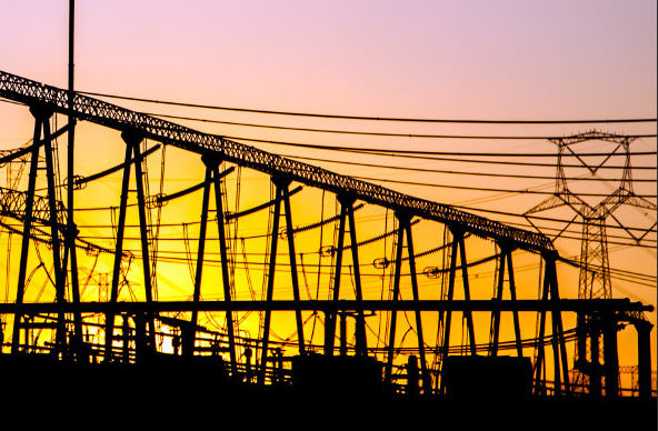
Timing & Substations
The new substation clocks typically run PTP/NTP over PRP but also include all the legacy signal to facilitate the integration of conventional substations and the new IEC 61850 standards by offering a wide variety of reference inputs and outputs.
MIAMI - SEPT 2022
Synchronization and Grid Automation
Time is an indispensable resource in grid automation required in critical applications such as Data Acquisition, Protection Relays Switchgears, SCADA, Events logging, Synchrophasors even in Virtual Plants to integrate renewable energy. The information, captured in real time at multiple points of the grid, must be processed and correlated. Only a perfect synchronization permits taking correct decisions to manage generation, transmission, distribution and protection resources, as a whole, to maintain a compact and effective power service. To achieve all these goals Net.Time provides a unified architecture aimed at guaranteeing the integrity of all the components in the electrical system, facilitating interconnection, stability and performance through a set of standardized protocols and information structures that will reduce commissioning and maintenance costs.
Synchronization aims to discipline clocks in a network to a common time reference:
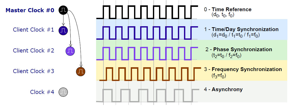
Fig 1. Types of synchronization
Master Clock #0
This is the time reference defined by a Day (d0), Phase (p0) and Frequency (f0)
Client Clock #1
It is disciplined to the Master on Day (d1), Phase (p1) and Frequency (f1)
Client Clock #2
It is disciplined to the Master only on Phase (p2) and Frequency (f2)
Client Clock #3
It is disciplined to the Master only on Frequency (f3)
Clock #4
It is not disciplined at all
Even when initially set accurately, real clocks will differ after some amount of time due to clock drift, caused by clocks counting time at slightly different rates.
Synchronization signals
Net.Time φ can synchronize by means of several signals that can be grouped according the following hierarchy.
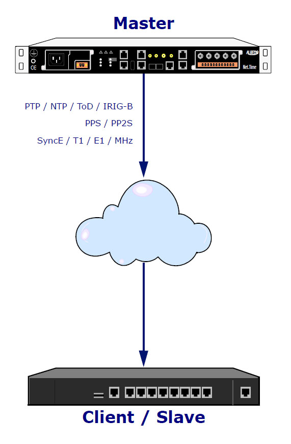
Fig 2. Timing is about references and disciplines.
1.. Time/Day Synchronization which is the most comprehensive as provide day, phase & frequency:
- PTP
- NTP
- ToD
- IRIG-B
- DCF77
2.. Phase or Time Synchronization can only provide phase and frequency:
- PPS
- PP2S
- PPnS
3.. Frequency Synchronization can only provide frequency
- T1
- E1
- SyncE
- MHz
DCF77 signal
Originally DCF77 is a German long-wave time signal and standard-frequency radio station that carries an amplitude-modulated data signal repeated every minute.
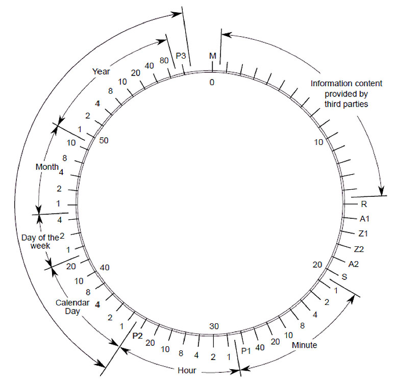
Fig 3. DCF77 frame.
- M: Start
- R: service request to the DCF77 system
- A1: forthcoming change CET to/from CEST
- Z1, Z2: time zone
- A2: Leap second bit
- Pi: parity bits
- S: Start of time information minute, hour, day, week day, months, year
A lot of substations generate the DCF77 signal synchronized with GNSS (or the time reference used in the node). The accuracy of DCF77 is good enough for SCADA and wall clocks and is still used.
IRIG-B signals
IRIG-B sends a timing signal at 100 pulse/sec rate including Year, Day, Hour, Min, Sec data with an update rate of one second direct or over a Carrier.
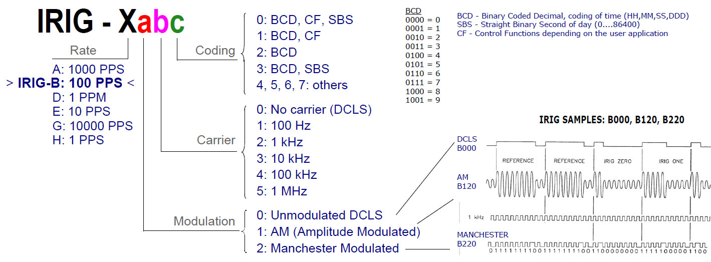
Fig 4. IRIG-B frame structure
Unmodulated DCLS IRIG-B offers several transmission alternatives:
- TTL-level signal over coaxial cable or shielded twisted-pair cable
- Multi-point distribution using 24 Vdc for signal and control power
- RS-485 differential signal over shielded twisted-pair cable
- RS-232 signal over shielded cable (short distances only)
- Optical fiber
T1/E1 signals
The T-carrier is a hardware specification for carrying multiple time-division multiplexed (TDM) telecommunications channels over a single four-wire transmission circuit. It was developed by AT&T at Bell Laboratories ca. 1957 and first employed by 1962 for long-haul pulse-code modulation (PCM)
digital voice transmission with the D1 channel bank.
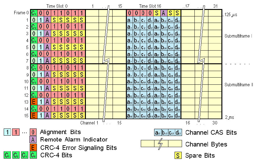
Fig 5. E1 frame structure
The E-carrier is a member of the series of carrier systems developed for digital transmission of many simultaneous telephone calls by time-division multiplexing. The European Conference of Postal and Telecommunications Administrations (CEPT) originally standardized the E-carrier system.
Mbit/s & MHz signals
Often known as BITS (Building Integrated Timing Supply) describe a building-centric timing system, the BITS system efficiently manages the number of timing interfaces within a structure providing external timing connections typically deployed as T1 or E1 frequencies but also can refer to MHz and then distributing timing to all circuits that require it.
Fig 6. Clock signals.
There are several signals suitable for transporting synchronization:
- Analog, of 1,544 and 2,048 kHz
- Digital, of 1,544 and 2,048 kbit/s
In both cases it is extremely important for the clock signal to be continuous.
SyncE protocol
Synchronous Ethernet is not part of the IEC 61850 but is required in the Power Grid and implemented by Net.Time.
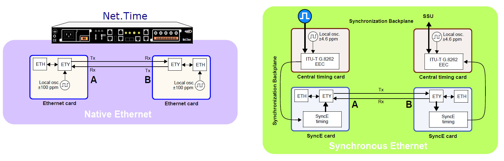
Fig 7. Synchronous Ethernet architecture
1. PHY Ethernet
- Rx gets synchronized using the input line [Tx (port B) >>> Rx (port A)]
- BUT there is no time relation between the Rx and Tx of the same Port
2. SyncE PHY (physical layer)
- Rx gets synchronized using the recovered clock
- Tx uses a traceable reference clock
NTP protocol
Network Time Protocol is intended to synchronize to within a few milliseconds using the intersection algorithm to select accurate time servers and is designed to mitigate the effects of variable network latency.
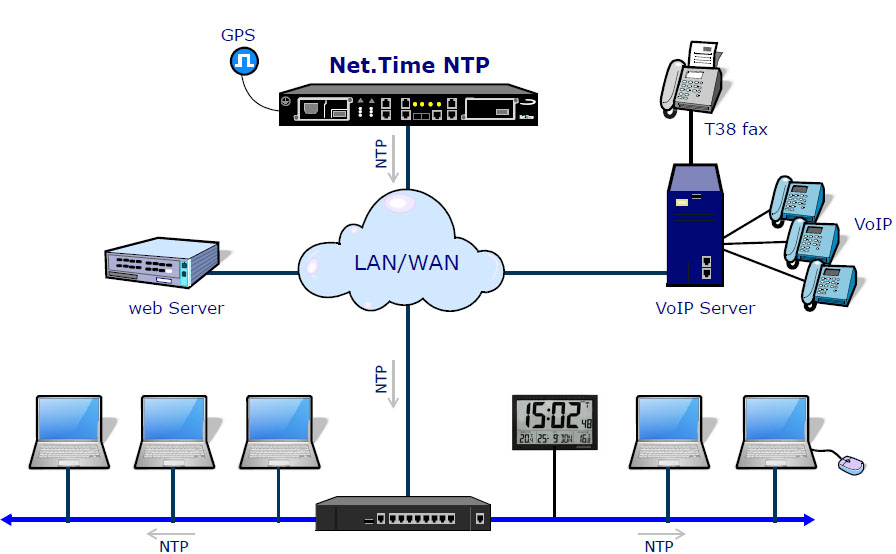
Fig 8. NTP in the substation is used for applications such as Scada.
NTP can usually maintain time to within milliseconds in local area networks under ideal conditions.
PTP protocol
Precision Time Protocol (IEEE 1588) is a cost-efficient solution and can be applied on the basis of the existing Ethernet network in a substation. PTP (IEEE 1588) applies master/slave time synchronization mechanisms and supports hardware time stamps.
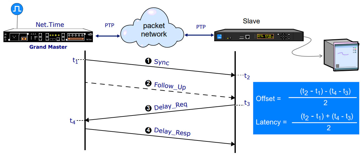
Fig 9. Precision Time Protocol procedure
The basic parameters of Latency / Offset are computed from the t1…4 stamps.
- Grandmaster sends a series of messages with date and time to client-clocks
- Client-clocks compensate the delays and get synchronized with the Master
- Frequency is then recovered with a precise time-of-d
- PTP prevents error accumulation in cascaded topologies, fault tolerance and enhances the flexibility and PTP can use an existing Ethernet reducing cabling costs and requires just a few resources.
Timing Evolution in the Substations
The peculiarity of the electricity companies, the high costs of their installations, the security and reliability and a certain inertia derived from technology and the economic exploitation regime, means that the inherited synchronism signals do not disappear overnight but rather keep for decades.
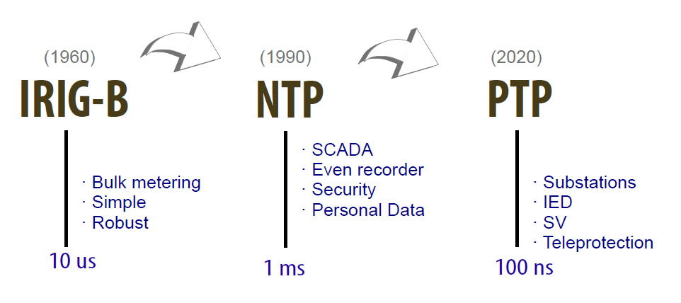
Fig 10. Timing evolution in Power Utilities
As result most of the Power Grid Timing has a combination of new and legacy synchronisation technologies.
Net.Time φ
This is a PTP/NTP over PRP clock designed to facilitate the integration of conventional substations based on GPS and IRIG-B with the new IEC 61850 standards by offering all kind of interconnection facilities.
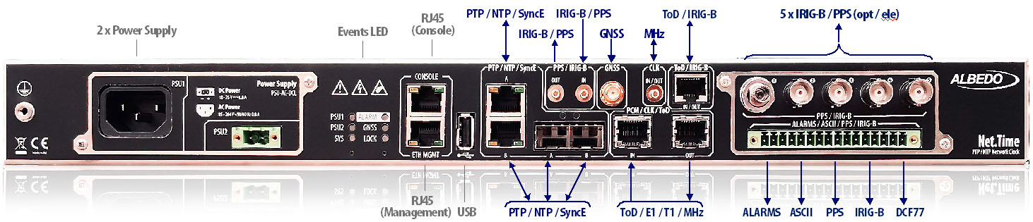
Fig 11. Net.Time Phi a utility network clock
Smooth migration to PTP
Many substations are adapting the IEC-61850 standards that consider PTP as the most advanced timing signal, however the installed base of signals such as IRIG-B, NTP, PPS among others, is so large that they will continue to be in operation for many years.
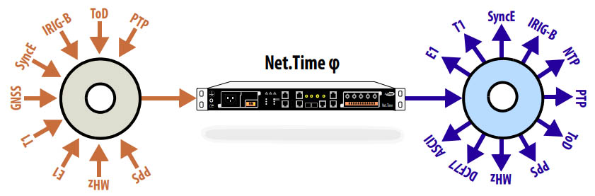
Fig 12. Universal timing translator.