Timing & Applications
The accuracy of a watch depends on the application. Anyone who wants to catch a train has to have an eye on the minutes. In competitive sport, a hundredth of a second can be decisive and a packaging machine may need microsecond accuracy.
MIAMI - JUNE 2019
Systems to be synchronized
There is a large number of industry applications that require to be synchornized:
- Mobile Back-haul
- Finance industry
- Stock Market
- Air Traffic Control
- Railways
- Broadcasting
- xGPON access
- Defense
- Manufacturing Plants
- Power Utilities
All the above mentioned systems require synchronization and must be equipped with internal clocks, however, nothing is perfect and a key effect has to be considered. Each clock, no matter how precise it may be, marks a different time, so the clocks must be constantly corrected to minimize the error and keep it within the required precision.
Finance industry

Financial institutions, hedge funds and market-makers need to address a variety of challenges with accurate, traceable time for their critical networks and network elements. High frequency trading requires real-time decisions based on microsecond time accuracy in order to remain competitive. This level of accuracy is available today through a combination of a GPS timing, new network synchronization protocol (PTP), PTP masters and slaves.
- Traffic in capital markets requiring accurate time pace of over one million per second.
- Trading decisions in real time environment use algorithms requires precision.
- Increasingly stringent regulatory oversight requiring high precision timed log files.
Energy production & distribution
The IEC 61850 standard for the design of electrical substation, includes NTP and, more importantly, PTP for timing to get accuracy below four milliseconds for protective relaying.
- In energy distribution systems, parameters such as currents and voltages are measured in distributed sensors, linked centrally and evaluated.
- Turbine controls use the PTP protocol to set up even more efficient plants.
- Monitoring processes, decentralize detected events are marked with precise time stamps and transferred to the control station for logging and analysis.
Railways
Modern railway engines consume energy when they start, but when they slow down or break the engine rotates backwards and therefore produces power back to the grid. Trains are moving around all the time so this is happening anywhere in the power grid network.

Accurate monitoring and time stamped measurements are essential to ensure optimal operation of converter stations at all times. This way power flows can be precisely analyzed and the converters can be fine-tuned to correct their static phase shifting properties and the dynamic behavior.
However, What the time is?
Time is a fundamental physical dimension that allows the chronological ordering and the distribution of resources.

Time is measured by counting an event that is repeated regularly, then it is measured by counting an event -physical or astronomical- that is repeated regularly:
- Astronomical events such as day, night, years
- Physical events such as a pendulum, resonance quartz or atomic transitions
Can we unify the time?
The time requires a reference to start counting at one common point, example: Gregorian calendar counts years from the birth of Christ, that gives a constant from a known epoch.

There are several Time Scales including:
- GMT (Greenwich Mean Time) which is based on the Earth rotation.
- UTC (Universal Time Coordinated) atomic accuracy must compensate the ‘unpredictable’ earth rotation.
- UAT (Universal Atomic Time) based on 200 atomic clocks and makes corrections.
- GPST (GPS Time) is a continuous time scale (no leap seconds) defined by the GPS Control segment on the basis of a set of atomic clocks.
- LORAN (Long Range Navigation Time) is an atomic time scale implemented by atomic clocks
- TAI (International Atomic Time) is a time scale that uses the combined output of some 400 highly precise atomic clocks
About Synchronization
Synchronization is the set of techniques that enable the frequency and phase of the equipment clocks in a network to remain constrained within the specified limits.
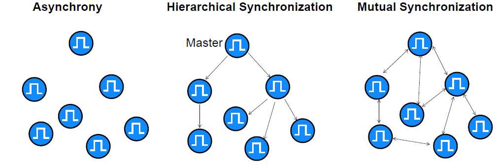
The first digital networks were asynchronous, and therefore did not call for properly working external synchronization. It was the arrival of SONET networks that started to make synchronization essential to maintain transmission quality and efficiency.
Time distribution
To synchronize a network of clocks to a master clock or reference signal, the signal must be distributed through a network.
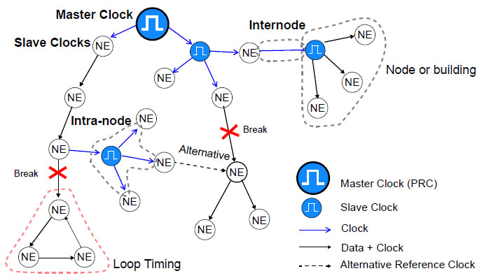
There are two basic ways to distribute synchronization across the whole network:
- Intranode, which is a high-quality slave clock known as either synchronization supply unit (SSU) or building integrated timing supply (BITS). These are responsible for distributing synchronization to NEs situated inside the node.
- Internode, where the synchronization signal is sent to another node by a link specifically dedicated to this purpose, or by an TDM signal or an Ethernet packet.
Sinchronization, Sintonization, Plesichrony
Depending on the relationship between the master clock and the disciplined clocks we can distinguish between:

- Asynchrony: there is no relationship between the clocks
- Syntonization: both clocks keep the same frequency
- Synchronization: both clocks maintain the same frequency and the same phase
- Absolute Synchrony: both clocks maintain the same frequency, phase, time and day.
IRIG-B
Developed for the US Army (1960) and it is widely used in Power Utilities and in some Air Traffic Control Systems. IRIG-B sends a timing signal every second at 100 pulse/sec rate therefore the 100 is the number of bits of each frame. IRIG-B info includes Year, Day, Hour, Min, Sec.
Physical Layer
● AM modulated clock reference input and output
● Unmodulated (DCLS) i/o over RS-422 / RS-485 or TTL
● Manchester encoded IRIG-B input and output

IRIG Frame Format
- Consists of 100 bits produced every second, 74 bits of which contain time information
- Various time, date, time changes and time quality information of the time signal
- IEEE-1344 extension included year data information
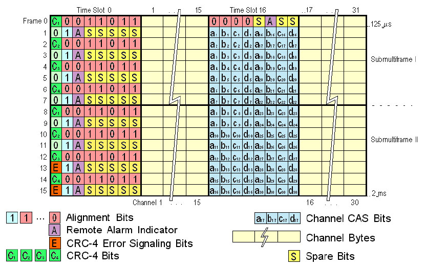
TDM Synchronization: E1 / T1
Can only provides frequency synchronization and was widely used in SONET/SDH networks and still is used in several industrial installations.
SyncE (Synchronous Ethernet)
Defined in ITU-T G.8261, G.8262, G.8264 can only provide frequency timing, it is accurate and used in Wireless and Power Utility networks.
Objectives:
- Inclusion of Ethernet (SyncE) as part of SONET/SDH synchronization network (G.8261)
- SyncE become slave clocks thanks to higheraccuracy, less noise and stability (G.8262)
- Extension of the Synchronization Status Message of SDH to SyncE by means of Ethernet Status Message Channel ESMC (G.8264)
The difference between conventional Ethernet is that SyncE is prepared to accept external timing
Synchronization moves from TDM to Packets
With TDM frames it is direct to obtain a regular pace (i.e. E1/T1 = 125us). However packets do not arrive regularly. Then how to synchronize? Ethernet Physical layer can be used, this is SyncE, but requires end-to-end continuity and it only transport frequency information. The alternatively is to timestamped packets, then phase and frequency can be distributed.
NTP (Network Time Protocol)
Network Time Protocol (NTP) is an Internet protocol for synchronizing the clocks of computer systems over packet network with variable latency.

- The clock frequency is then adjusted to reduce the offset gradually, creatin
- Precision 1 – 10 ms. in Internet, (0,5 – 1 ms for LAN ideal conditions)
IEEE 1588 PTPv2
The idea for PTP was born at the end of the 90s in the USA at Agilent Technologies in the field of measuring technology.

The process principle developed there was submitted to the IEEE as a suggestion and created the basis for the IEEE 1588 standard. At the end of 2002 PTP was passed as a standard under the name of “1588TM – IEEE Standard for a Precision Clock Synchronization Protocol for Networked Measurement and Control Systems“. In addition, PTP was also adopted as an IEC standard in May 2004 and was published under the name of IEC 61588.
- Grandmaster sends a series of messages with date and time to client-clocks
- Client-clocks compensate the delays and get synchronized with the Master
- Frequency is then recovered with a precise time-of-day
PTP – Precision Time Protocol (IEEE 1588)
 The basic parameters of Latency / Offset are computed from the t1…4 timestamps
- The precision is achieved
– Frequent Packets (up to 128 per second)
– Hardware Timestamp (NTP is software) - Best Master Clock algorithm
Mobile networks 5G and LTE
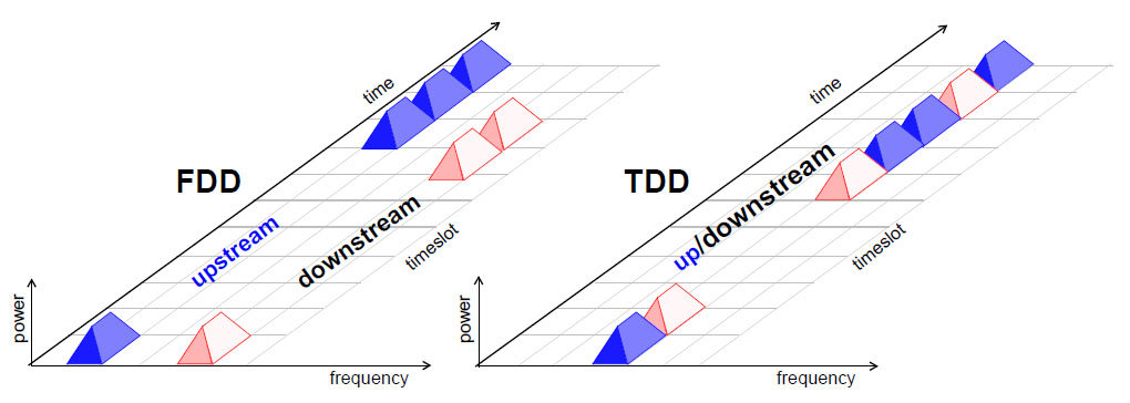
- In FDD duplexing upstream and downstream use separate frequencies
- In TDD upstream and downstream share the frequency (more efficient use bandwidth)
- Then FDD requires only Syntonization (frequency)
- TDD requires Phase Synchronization (phase and frequency)
Jitter and Wander
Jitter of a clock signal is defined as the variations in phase whose frequency component is greater than 10 Hz, while Wander is the variations in phase at rates less than 10 Hz. See below the graphical definition of Jitter and Wander

Two Samples
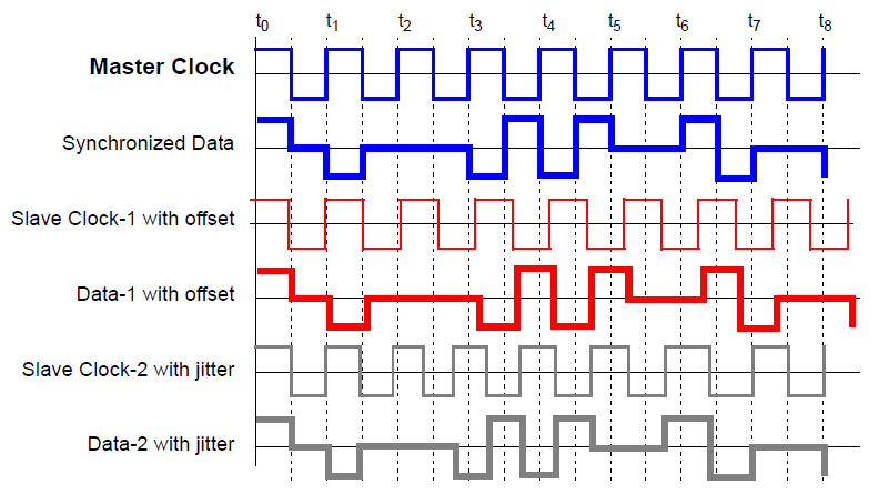
A master clock that marks the significant instances for data transmission.
- Clocks 1 and 2 are badly synchronized
- Data transmitted with these references is also affected by the same phase error.
Timing Alignment in Wireless
- When hand-over occurs, the mobile must reacquire carrier frequency
– Large Df compromises the reliability of hand-over; 50 ppb typical requirement - TDD networks require time/phase alignment between A & B
– To control interference between uplink and downlink
– Requirement in the microsecond range
– To avoid time overlapping requires phase synchronization 1.5 us - TDD networks require time/phase alignment between A & B
– To control interference between uplink and downlink
– Requirement in the microsecond range
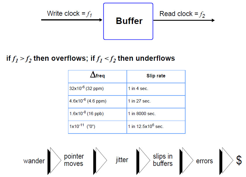
TDM Slips
Time Error (TE)
Time Error (TE) is the difference between the announced time and its time reference:
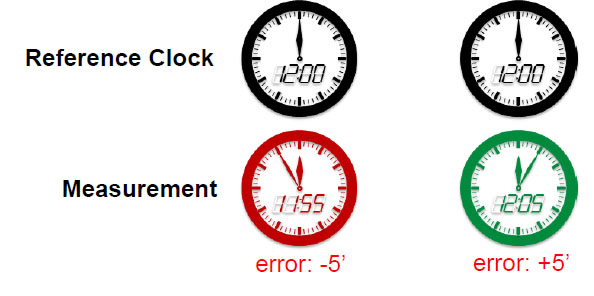
- It is a relative measurement because it does not make sense without reference
- Defined by the ITU-T Recommendation G.810
x(t) = T(t) -Tref(t)
x(t): error
T(t): time in the clock
Tref(t): reference time
Time Interval Error (TIE)
TIE is the basic measure of wander used in TDM, the unit is the nanosecond. TIE gives the instantaneous phase error in f(t) from the start of the measurement TIE (t0) = 0
It is not relevant in itself but its calculation is prior to the remaining measures.
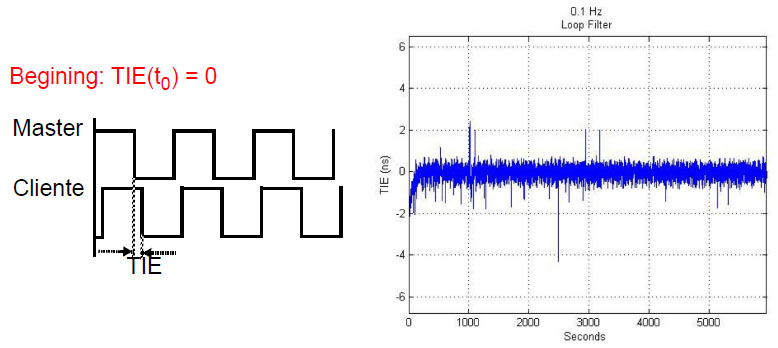
Appropriate for measuring quality because the reference frequency is the beginning of the measure while TE is requires an absolute scale such as TAI or GPS
MTIE: Maximum TIE
MTIE measure the amplitude of the TIE variation
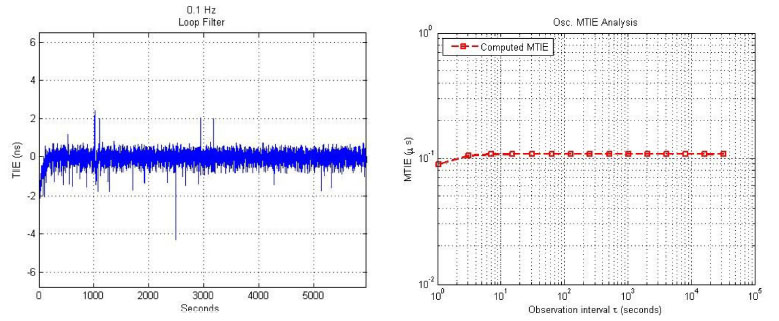
It is useful to calculate the buffer size to filter the wander.
Packet Filtered MTIE (is an algorithm equivalent to MTIE at the packet interface)
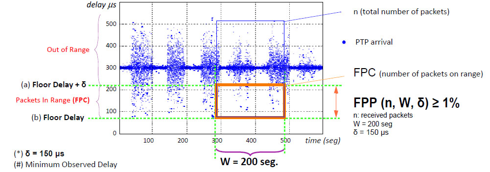
Floor Packet Measurements (ITU G.8271.1)
