
RELATED POSTS
RELATED PRODUCTS
MORE INFO
Jitter control in T1 & E1 lines
Controlling jitter in E1 and T1 lines is required for maintaining the reliability, accuracy, and quality of digital communication ensuring proper synchronization, data integrity, and performance in timing, voice and data applications.
BARCELONA NOV.20.2023
Pulse Code Modulation
Pulse Code Modulation (PCM) technology was patented and developed in 1938, but could not be used because suitable technology was not available until World War II. This changed with the advent of digital systems in the 1960s, when improving the performance of communications networks became a real possibility. However, this technology was not fully adopted until the mid-1970s due to the large number of analog systems already in use and the high cost of digital systems, as semiconductors were very expensive. The initial goal of PCM was to convert an analog voice telephone channel to digital based on the sampling theorem.
PDH and T-Carrier
In the early 1960s, the proliferation of analog telephone lines based on copper wires, combined with the lack of space for new installations, led transmission experts to consider the real-world application of PCM digitization techniques and TDM multiplexing. The first digital communications system was built by Bell Labs in 1962 and consisted of 24 digital channels running on a so-called T1.
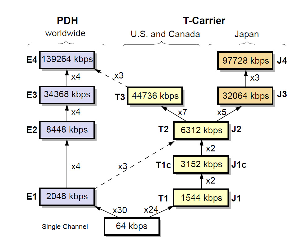
Fig 1. PDH and T-carrier hierarchies.
Basic Rates: T1 and E1
In 1965, a standard appeared in the U.S. that permitted the TDM multiplexing of 24 digital telephone channels of 64 Kbps into a 1.544-Mbps signal with a format called T1. For the T1 signal, a synchronization bit is added to the 24 TDM time slots.
Europe developed its own TDM multiplexing scheme a little later (1968), although it had a different capacity: 32 digital channels of 64 Kbps. The resulting signal was transmitted at 2.048 Mbps, and its format was called E1 which was standardized by the ITU-T and adopted worldwide except in the U.S., Canada, and Japan. After the obsolescence of the TDM networks interestingly T1 remains in the industry because one of the most important applications of E1 is timing to synchronize devices and systems.

Fig 2. PDH and T-carrier hierarchies.
The E1 Frame
The E1 frame defines a cyclical set of 32 time slots of 8 bits. The time slot 0 is devoted to transmission management and time slot 16 for signaling; the rest were assigned originally for voice/data transport. After the obsolescence of the TDM networks interestingly E1 also remains in the industry because one of the most important applications of E1 is timing to synchronize devices and systems.
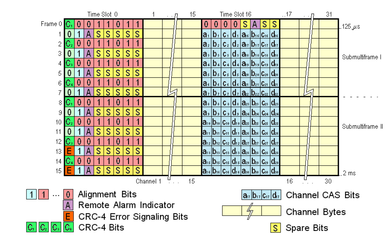
Fig 3. The E1 frame is the first hierarchy level.
Controlling jitter in E1 and T1 lines
This is important for maintaining the reliability and quality of communication in digital transmission systems. Jitter refers to the variation in the timing of signal arrivals, and it can have significant implications for the performance of these communication lines. Here are several reasons why controlling jitter is crucial:
- Timing Accuracy: E1 and T1 lines are widely used for digital voice and data communication. In applications such as telephony, precise timing is crucial for maintaining the integrity of voice signals and ensuring that data is transmitted and received accurately. Controlling jitter helps maintain timing accuracy, reducing the risk of signal degradation.
- Synchronization of Communication Devices: Jitter can disrupt the synchronization between transmitting and receiving devices. In systems where multiple devices need to operate in harmony, such as in a network or telecommunications infrastructure, controlling jitter ensures that devices stay synchronized, preventing issues like packet loss or data corruption.
- Data Integrity: Jitter can lead to misalignment of data symbols, causing errors in the received signal. By controlling jitter, the likelihood of errors is minimized, ensuring the integrity of the transmitted data. This is particularly important in applications where data accuracy is critical, such as in financial transactions or data transfer over wide-area networks.
- Voice Quality: In voice communication over E1 and T1 lines, jitter can cause disruptions, echo, or jitter-induced artifacts in the audio signal. Controlling jitter is essential for providing clear and high-quality voice communication, especially in applications where voice clarity is paramount, such as in teleconferencing or Voice over IP (VoIP) systems.
- Network Performance: Jitter can affect the overall performance of a network by impacting the flow and timing of data packets. Uncontrolled jitter can result in packet loss, increased latency, and degraded network performance. By controlling jitter, network administrators can ensure a smoother and more reliable data transmission.
- Compliance with Standards: Telecommunication standards often specify requirements for jitter in E1 and T1 lines. Adhering to these standards ensures interoperability between different network components and devices. Controlling jitter is a key factor in meeting these standards and promoting compatibility in communication systems.
In summary, controlling jitter in E1 and T1 lines is essential for maintaining the reliability, accuracy, and quality of digital communication. It plays a critical role in ensuring proper synchronization, data integrity, and overall performance in various applications, from voice communication to data transfer in telecommunications and networking environments.
AT-One
The AT.One is the ultimate tester designed specifically for field engineers that are installing, commissioning and trouble-shooting T1/E1 and Datacom circuits. The AT.One has been designed and manufactured by ALBEDO Telecom in a brand new platform incorporating the latest available electronics. Consequently you will enjoy top performance, high accuracy and, of course, a very competitive price.
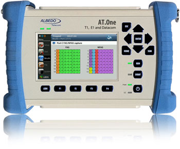
Fig 4. The AT-One is the ultimate TDM to verify T1 and E1.
The AT.One analyzer is a simple to use, rugged handset, equipped with a full color GUI specifically designed for field use for the analysis and maintenance of telecom circuits. Its comprehensive performance includes framed and unframed signalling, drop and insert Nx64Kbps, data and jitter into any time slot.
xGenius and Zeus
xGenius and Zeus testers provide in-depth insight into the design, installation, maintenance, troubleshooting and engineering of Smart Grid communications infrastructures. The unit can test Ethernet/IP, PTP, GbE, IRIG-B, T1/E1, G703, C37.94 and GOOSE, SV and MMS protocols. One-way delay testing, supported by GPS, is available on all interfaces. Zeus has a set of programmable filters to capture live traffic at wire speed. You can now analyse GOOSE, SV, MMS and other protocols to decode and store them in PCAP format or calculate propagation delay from local or remote substations.
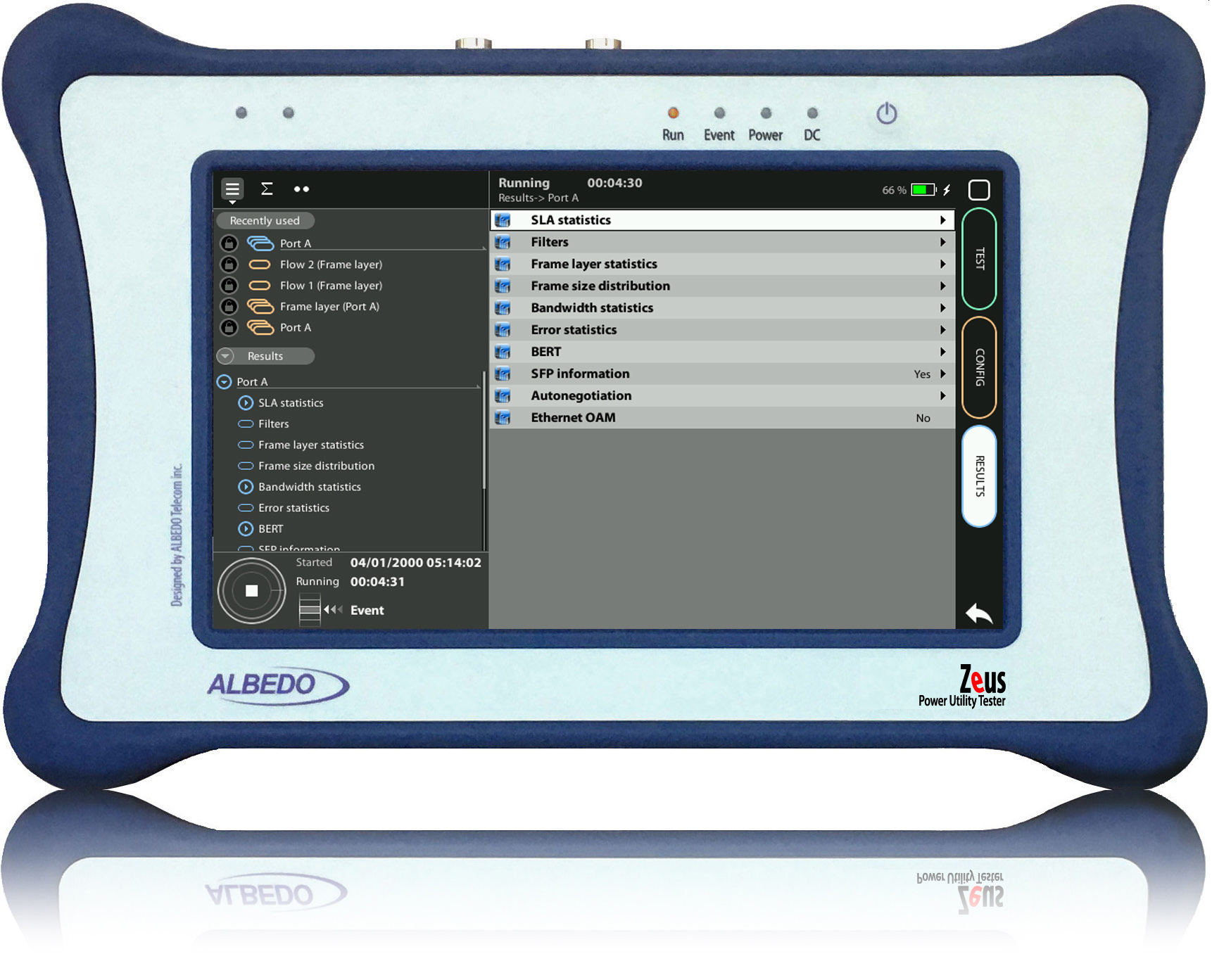
Fig 4. Zeus the favorite tester of field engineers support E1 and T1.