
RELATED POSTS
RELATED PRODUCTS
PTP Time Error Budget Calculator
Estimate how source clock accuracy, Boundary/Transparent Clock accumulation, network asymmetry, packet delay variation, and substation clock noise affect the final PTP time error margin at an IED.
UIO - JUL 01, 2026
The reference architecture shows time distributed from a central GNSS-disciplined PRTC/T-GM across a carrier WAN to each substation. At the substation, a local APTS clock bridges the telecommunications timing domain and the substation LAN. Each element in this chain, including the Grandmaster, boundary or transparent clocks, fiber links, and packet network delay variation, contributes to the accumulated time error observed at the IED inputs.
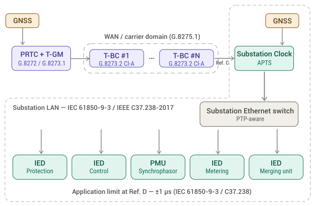
Fig. 1 PTP Time Synchronization Distribution Architecture for Substation Deployment
Calculator inputs
Source Clock: PRTC / T-GM
The PRTC is the starting point of the time traceability chain and is typically disciplined by GNSS. The calculator supports PRTC-A, PRTC-B, and ePRTC classes. The T-GM converts the reference timing signal into PTP messages and adds its own noise contribution to the PRTC output.
Network Impairments
Network impairments are timing errors introduced by the transport path. Link asymmetry is the delay difference between the forward and reverse PTP paths and appears as a fixed cTE offset. PDV residual is the dynamic timing noise that remains after packet selection and filtering at the slave clock.
T-BC / T-TC Chain
The timing path may include Telecom Boundary Clocks, Transparent Clocks, or both. A T-BC terminates and regenerates PTP at each hop, which helps control packet delay variation but adds a per-node time error contribution. A T-TC preserves the end-to-end PTP relationship by updating the correction field with its residence time, but it does not filter packet delay variation in the same way as a T-BC.
Substation Clock and Application
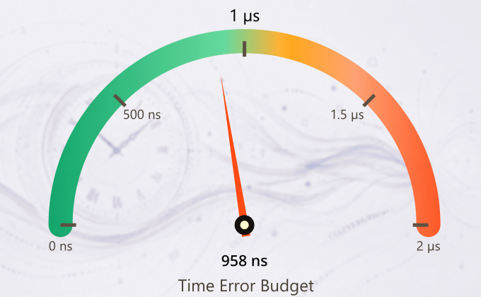
The substation clock bridges the carrier PTP domain and the local IED network. Its servo and oscillator add the final timing contribution before the IED receives the timing signal. The application limit defines the maximum acceptable time error at the IED input, commonly ±1 µs for IEC/IEEE 61850-9-3 and IEEE C37.238-2017 applications.
Time Error Calculator
The calculator below models this accumulation interactively. To use it, first confirm the substation clock noise, the TC residence time error and the IED application limit. Then, select the PRTC class and adjust the T-GM noise contribution. Next, define the number and class of T-BC/T-TC hops and add the expected link asymmetry and PDV residual. The stacked bars will update in real time to show the total TE budget and the cTE-only stack, representing the worst-case linear accumulation used for standards-based planning.