

RELATED POSTS
RELATED PRODUCTS
MORE INFO
PTP Telecom Testing Guide
The challenges of delivering the PTP telecom profile with the required accuracy are important in Ethernet / MPLS networks. There is also a renewed interest in time testing for both network commissioning and troubleshooting.
ODT DEC.01.2023
PTP Testing Overview
Accurate frequency distribution over packet-switched networks can be thought of as an extension of the TDM synchronization network based on a few new building blocks such as the Synchronous Ethernet Equipment Clock (EEC) and the Packet-based Equipment Clock (PEC). However, this approach does not work for time and phase distribution applications, where most of the interest is today. This paper reviews existing test techniques applicable to frequency distribution and introduces the new techniques for phase and time applications. A minimal description of the technologies that enable accurate phase and time distribution, including the Precision Time Protocol (PTP), is also covered.
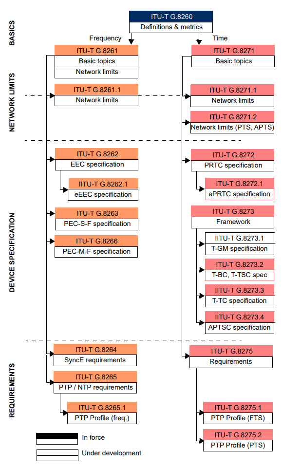
Fig 1. ITU-T network timing and synchronization standards.
PTP Telecom Profiles
PTP plays a central role in most time and phase synchronization architectures and is the key technology in all current applications that require a high degree of accuracy, typically in the range of a few microseconds and sometimes in the sub-microsecond range. The IEEE 1588-2019 standard, in which PTP is defined, is flexible enough to allow for many different uses of the protocol, including both frequency and time distribution applications. Because of its flexibility, PTP can operate in different profiles. These profiles are not interoperable; they provide different levels of performance and impose different requirements on the network. As stated in IEEE 1588-2019, the purpose of a PTP profile is to allow organizations to define a specific set of attribute values and optional features of PTP that, when using the same transport protocol, will work together to achieve performance that meets the requirements of a particular application.
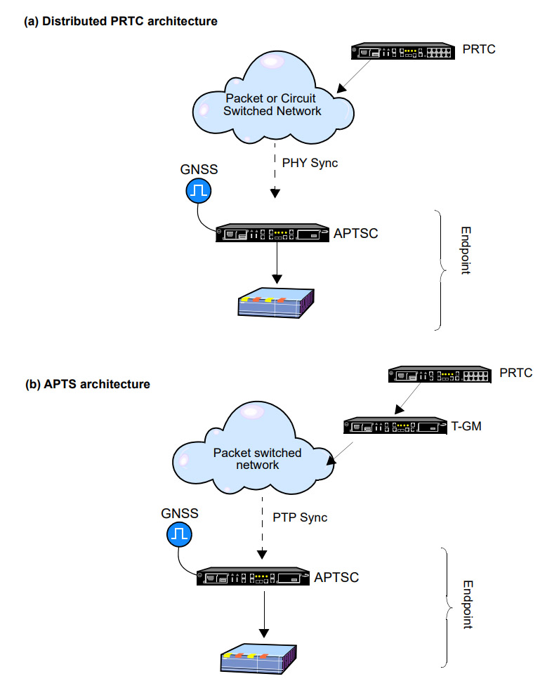
Fig 2. Comparison between the legacy distributed PRTC and APTS architectures.
The ITU-T G.8265.1 Frequency Profile
The purpose of the ITU-T G.8265.1 PTP Frequency Synchronization Profile is to adapt PTP to the common practice of telecommunications network synchronization. The purpose of this profile is not to provide better performance than any previous protocol or to define new functionality in the synchronization network, but to extend the existing network to include PTP as a protocol suitable for carrying synchronization with minimal impact on the installed infrastructure based on TDM technology (or Synchronous Ethernet).
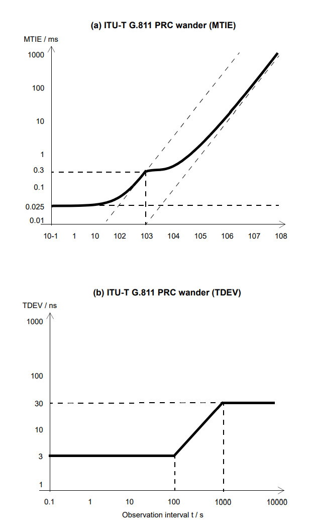
Fig 3. ITU-T G.811 performance limits of a PRC expressed in terms of MTIE and TDEV.
An interesting feature of the ITU-T G.8265.1 profile is the ability to operate in one-way mode. PTP masters use the Sync message flow to exchange time stamps with their peers (slave clocks, boundary clocks). When time synchronization between the master and its peers is required, the time it takes for the remote end to receive the time stamp must be compensated for in some way. This is done by either the end-to-end or peer-to-peer path delay mechanisms. If no time synchronization is required, there is no need to apply delay compensation and the message flows associated with the path delay mechanism can be removed. This one-way mode of operation is allowed by IEEE 1588-2019 and is optional within ITU-T G.8265.1.
Testing Challenges
There are at least five critical blocks or functions in any synchronization test set: the local oscillator, the clock reference, the network emulator, the test engine, and the post-processing unit. Each block presents its own challenges for reliable and accurate testing:
- Local oscillator: The local oscillator is an internal frequency source required by any synchronization test equipment. The local oscillator is expected to be accurate within certain limits. It could theoretically be used as an autonomous (internal) reference, but most of the time the local oscillator is locked to another clock reference. In this case, the local oscillator inherits some of the characteristics of the reference. A typical situation is to discipline the local oscillator with a GNSS source. In this case, the local oscillator is expected to achieve the long-term frequency/time accuracy of the GNSS source.
- Clock Reference: Sometimes, as in jitter testing, the clock reference can be recovered from the signal under test by some kind of filtering, but more often the clock reference is an independent input to the test. Two main alternatives are used in practical scenarios: Primary Reference Clocks (PRCs) / Primary Reference Time Clocks (PRTCs) and Global Navigation Satellite System (GNSS) signals.
- Network emulator: The test set needs to be connected to a device or network to be measured, and to some extent it needs to be compatible with the system to which it is connected. Sometimes it is sufficient to achieve interface compatibility, as in TDM or 1PPS testing, but in other situations both interface and protocol compatibility are required. The most typical example of protocol compatibility is PTP testing, which requires the test set to be interoperable not only with the physical interface (typically Ethernet and IP), but also with the PTP protocol itself. Specifically, in most cases, the test set must implement some of the functionality of a PTP slave. It must not only decode timing information from remote PTP devices, but also generate various types of PTP messages, such as signaling messages and delay request messages.
- Test Engine: The purpose of any test instrument is to take a measurement and generate a result based on that measurement. In a synchronization tester, the test results consist of a sequence of numbers calculated by comparing a relative or absolute time associated with the device under test and the time of the clock reference. For a typical drift measurement, the tester can generate tens or hundreds of test results per second. The exception to this rule is jitter, which is a high-frequency phase disturbance. The measurement bandwidth for jitter is in the kHz range or beyond and requires a different approach.
- Post Processing Unit: This building block calculates synchronization performance metrics from the raw measurement results. Many sources of interference are either random or difficult to predict (variable wait time in queues, oscillator noise, variations in GNSS coverage, temperature variations). For this reason, the associated performance metrics are statistical in nature. Some common statistics are general-purpose metrics such as mean or standard deviation, while others are defined specifically for synchronization applications, such as Allan Deviation (ADEV) or Time Deviation (TDEV). The randomness of synchronization test results is a challenge in terms of repeatability. For example, estimates of the standard deviation of some types of phase noise do not converge to a specific value even over very long tests; there is no way to measure (or even define) a standard deviation for such processes.
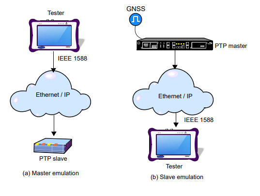
Fig 4. Basic PTP testing scenarios in endpoint mode: (a) Master emulation mode, (b) Slave emulation mode.
Synchronization Tests
Synchronization tests can be divided into emulation and monitoring tests. In an emulation test, the test set behaves as a specific network element (or group of elements) and sometimes replaces that entity. Typically, the test set is not required to replicate all the functionality of the emulated device, but on the other hand, the tester is able to perform some diagnostics beyond the capabilities of the emulated device. Depending on the equipment connected to the network and the entity being emulated there are four basic test setups:
- Master emulation: The device emulates a PTP master. The main purpose of this mode is not to perform measurements, but to stress the network, including the slave. In fact, in this mode, the probe only receives delay request messages (in some profiles, the path delay mechanism may be disabled and therefore not even delay request messages are received), which do not contain enough information to perform a detailed performance analysis.
- Slave emulation: In this case, the tester replaces the slave. The tester processes the information received from the master and tries to follow the timing signal in the same way as any other PTP slave clock. This mode can be used to obtain message statistics, verify basic conformance, and obtain some PDV metrics such as packet delay variance, standard deviation, and range. Slave emulation mode is not suitable for more sophisticated performance tests involving MTIE, TDEV, and TE. It is difficult to measure MTIE and TDEV in this mode because the test unit is being disciplined by a device that is also the device under test.
- Pseudo-Slave Emulation: This mode is similar to slave emulation mode, but now the test unit maintains an independent synchronization source. Typically a GNSS reference is used, but the test equipment can use any other reference such as 1PPS / ToD, frequency inputs, or even an internal oscillator in holdover / free running states. Outwardly, the pseudo-slave and slave emulation modes are indistinguishable, but internally they are different.
- Clock Monitor: It is good for a test set to support at least some kind of passive test mode. This mode could be the monitoring of clock interfaces. The monitored signals should include both frequency (2048 kb/s, 2048 kHz, 1544 kb/s, 1544 kHz, 10 MHz) and time (1PPS / ToD). The performance metrics in these interfaces are similar to those in Ethernet/IP ports. Traditional MTIE and TDEV are used, rather than their versions for packet interfaces, and TE could be reused almost without modification.
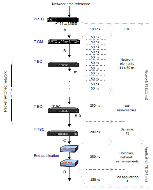
Fig 5. Time Error in a phase / time delivery application.
Time and phase testing
Time and phase testing is where most of the interest is today, but it is also an area with significant test challenges. The TE limit for a PRTC-A is 100 ns or 40 ns for a PRTC-B. For ePRTCs, the maximum TE is 30 ns, equivalent to the propagation delay of an electrical signal over 5-6 m of coaxial cable. Measuring these minute times requires a highly accurate time/phase reference and carefully designed measurement engines. The fractional frequency offset and ground delay population are not relevant in phase/time applications. In fact, a frequency offset of 1 ppb produces a phase error equivalent to about 90 ms in a day, much more than the accuracy required in this type of deployment. Along with MTIE and TDEV, TE is the most important phase/time performance metric.
Fig 6. ITU-T G.8260 metrics derived from the raw TE.
Network limits for phase and time applications are defined in ITU-T G.8271.1; limits for isolated units (PRTCs, ePRTCs, T-GMs, T-BCs, etc.) are spread over several standards. This document focuses on network limits and the applications considered in ITU-T G.8271.1. Among the most important of these applications are 4G and 5G cellular systems, which require a phase accuracy of 1.5 ms or better.
To ensure that the phase offset between any two base stations or Enhanced Node-Bs (eNBs) remains within specified limits, the entire network must be carefully designed. Each network element (and even the transmission medium!) is constrained to certain operational limits in terms of TE. The network operator is expected to take into account the TE already present in the PRTC/T-GM, the variable TE due to random phase noise processes, and the TE generated at the application end. If a critical device loses all external clock references, it will enter a holdover state and start drifting. This condition should be planned for from the beginning and some margin should be reserved to accommodate temporary holdover in the timing distribution equipment. All of these performance considerations make up the so-called TE budget for the deployment.
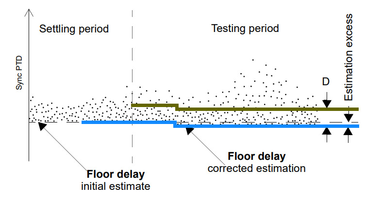
Fig 7. Floor delay population test.
MTIE and TDEV
MTIE and TDEV are still important performance metrics in phase/time distribution deployments, but the way they are used in this case is slightly different. In the same way that a constant frequency offset requirement could be added to the MTIE mask by a straight line with a specific slope, a phase requirement could be added by a horizontal line, where the phase offset requirement is the distance of the line from the horizontal axis. This approach is used in the ITU-T G.8271.1 and G.8272 standards, among others. The PRTC MTIE is up to 100 ns, and the T-TSC MTIE includes components up to 580 ns.
The ability of MTIE and TDEV to qualify slow TE is explicitly used in some standards, such as ITU-T G.8273.2, which is basically dedicated to T-BC and T-TSC performance requirements. This standard defines a separate limit for cTE (continuous TE frequency component) and for “slowly varying dynamic TE”, referred to as dTEL, which includes all low-frequency TE (typically up to 0.1 Hz) but does not include the continuous component. The MTIE and TDEV are very good at evaluating dTEL in both constant temperature (CT) and variable temperature (VT) environments.
Testing the PTP Clock
xGenius and Zeus can be configured to act as PTP slave clocks. There is no difference between a standard PTP clock and these devices, but the testers provide measurement results that are useful for qualifying the stability of a PTP clock source. In pseudo-slave emulation mode, the device behaves as a PTP slave, but maintains an independent synchronization source that allows the device to calculate TE and other performance metrics such as MTIE/TDEV based on the comparison of the phase and frequency of the test signal to the clock reference input. The following description assumes that the instruments are configured with factory default settings.
The testers can also measure the quality of the PPS output and will also verify the TE and MTIE/TDEV of this signal.
Fig 8. Zeus and xGenius are the two most popular and featured testers to test PTP.
ALBEDO PTP testers
ALBEDO xGenius is a multitechnology tester equipped with 8’ screen and all the features you need to install and maintain telecom networks up to 10Gigabit Ethernet It supports legacy and new generation interfaces in order to verify Ethernet / IP, PTP, SyncE, ToD, IRIG-B, T1 / E1, C37.94, RS-232, G703 and check protocols such as GOOSE, SV or MMS. It is suitable for measuring legacy and next-gen networks as it has the most common interfaces. Field engineers do not need to carry any more several testers or multiple modules to turn up and monitor telecom infrastructures.
xGenius is equipped with all of the features you may need or imagine such including BER, RFC2544, eSAM, Multistream, MPLS, Jitter, Wander, etc. to permit the verification of the transmission layer in those terms of performance and quality required to support audio, video or critical data applications.
Built-in Rubidium / GPS clock
The integrated GPS/GLONASS receiver allows easy connection and use while fast acquisitions and excellent accuracy minimizing the time impairments of external devices. This an ideal solution to synchronize thanks to top performance in holdover mode while top accuracy in a real hand-held battery operated IP tester.