

RELATED PRODUCTS
MORE INFO
SONET / SDH: sophistication in TDM
SONET / SDH and Ethernet serve different purposes in the realm of telecommunications, and each has its own advantages and disadvantages. While Ethernet has become the dominant technology SONET / SDH continues to be utilized in certain scenarios.
HIGH WYCOMBE (UK) NOV.23.2023
SONET / SDH vs. Ethernet
SONET (Synchronous Optical Network) SDH (Synchronous Digital Hierarchy) and Ethernet serve different purposes in the realm of telecommunications, and each has its own advantages and disadvantages. While Ethernet has become the dominant technology for local area networks (LANs) and is widely used for many applications, SONET continues to be utilized in certain scenarios for several reasons:
- Reliability: SONET/SDH was designed with a focus on reliability and fault tolerance. It includes features like automatic protection switching (APS) and fault detection mechanisms that make it well-suited for critical links. This is especially important for applications where network downtime is not acceptable, such as in power utilities, financial transactions, and other mission-critical systems.
- Timing: SONET/SDH is synchronous, which means that devices can be synchronised by extracting the timing from the physical layer. This is interesting but has some limitations as it is only frequency, not phase. Ethernet has the SyncE version, which is equivalent in this respect, but in its traditional form does not provide timing, which is provided by specific protocols such as NTP or PTP.
- Transmission: SONET/SDH was designed for long-haul, high-speed data transmission over optical fibers. While Ethernet is suitable for local and metropolitan area networks, SONET used to be often preferred for backbone networks that span longer distances. Nevertheless this has changed during the last decade and today Ethernet also scales to long-haul.
- Legacy : Many existing networks are built on SONET infrastructure. Upgrading an entire network infrastructure can be a complex and expensive process. As a result, SONET is still used in some cases to maintain compatibility with existing equipment and to leverage the investment made in SONET-based infrastructure.
- Predictible: SONET/SDH networks often provide well-defined reliability, latency, and other performance metrics. For certain applications such as Teleprotection with stringent requirements, SONET/SDH may be the preferred choice.
- Security: SONET/SDH networks are known for their security features, making them suitable for applications where data integrity and confidentiality are critical.
Ethernet has been evolving to address some of these limitations. Carrier Ethernet, for example, is an extension of Ethernet technology designed to meet the requirements of telecommunications carriers, offering improved determinism and reliability. As technology continues to advance, the choice between SONET and Ethernet will depend on specific use cases, network requirements, and the existing infrastructure in place. In many cases, there is a trend toward transitioning to Ethernet-based solutions, but SONET remains relevant in certain contexts.

Fig 0. SONET / SDH and Ethernet serve different purposes in telecoms.
SONET and SDH
Synchronous digital hierarchy (SDH) is an ITU-T universal standard that defines a common and reliable architecture for transporting telecommunications services on a worldwide scale. Synchronous optical network (SONET) is today a subset of SDH, promoted by American National Standards Institute (ANSI) and used in the U.S., Canada, Taiwan, and Korea. From now on we will use the acronym SDH to refer to the generic ITU-T standard that includes also SONET.
The Emergence of SDH/SONET Networks
During the 1980s, progress in optical technologies and microprocessors offered new challenges to telecommunications in terms of bandwidth and data processing. At that time, plesiochronous hierarchies (T-carrier and PDH) dominated transport systems, but a series of limitations and the necessity to introduce new transmission technologies moved to develop a new architecture.
Antitrust legislation was the final factor that hastened the development of SONET. It was applied to the telecommunications business and forced the giant, Bell, to be split up into small companies, the regional Bell operating companies (RBOCs). SONET, developed at Bellcore labs in 1984, grew out of the need to inter-connect RBOCs using standardized optical interfaces. Telecom liberalization was confirmed around the world during the ‘90s, and this has inevitably led to global competition and interoperation.
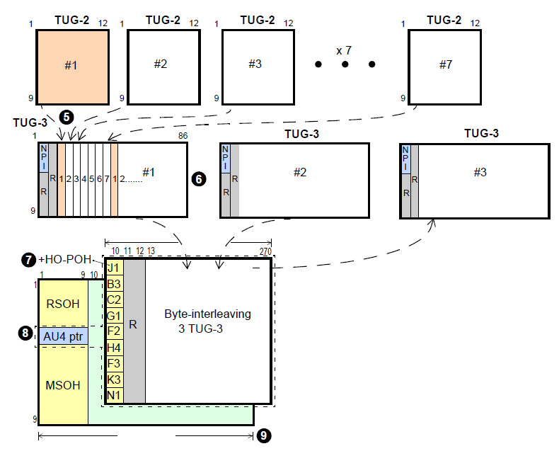
Fig 1. Synchronous and asynchronous transport of a 2-Mbps circuit.
The SDH/SONET Challenge
What had to be decided first was how to provide smooth migration from legacy installations. Then a basic frame period of 125 ms was selected, the same of E1 and T1 frames, in order to guarantee compatibility with existing services such as plain old telephone service (POTS), integrated services digital network (ISDN), frame relay (FRL) or any n x 64 Kbps. Note that a byte constantly carried on a 125-ms frame period defines a 64-Kbps channel. Some of the remarkable features of SDH compared with its predecessors are:
- Synchronous versus plesiochronous: Plesiochronous means “almost synchronous.” This in its turn means that nodes try to do work in the same frequency, but in fact they do not, because each PDH island use its own clock. In synchronous networks, all digital transitions should occur simultaneously, and all the nodes must be fed with the same master clock (see Chapter 5 in the book). There may, however, be a phase difference between the transitions of the two signals but this must lie within standardized limits.
- Bytes versus bits: In SDH and SONET, such basic operations as multiplexing, mapping, or alignment are byte oriented, to keep transported elements identified throughout the whole transmission path.
- Direct access. The main difference between SDH and its predecessors is in synchronization and byte-oriented operations. Synchronization enables us to insert and extract tributaries directly at any point and at any bit rate, without delay or extra hardware. For this reason, PDH/T-carrier must completely demultiplex signals of various megabits per second, to access any embedded channel of n x 64 Kbps.
- Full management. In SDH and SONET, payload and overheads are always accessible, and there is no need to demultiplex the signal. This drastically improves operation, administration, and maintenance (OA&M) functions, which are essential to enable centralized management independently of the bit rate.
SDH and SONET also provide embedded mechanisms to protect the network against link or node failures, to monitor network performance, and to manage network events. - Providing circuits for public networks: The basic function of SDH, just like any transmission network, is that of providing metropolitan or long-haul transport to networks. Signaling, switching, routing, and billing do not depend on SDH, as it is only in charge of providing bandwidth between two points.
- Universal standard: SDH and SONET standards enable transmission over multiple media, including fiber optics, radio, satellite, and electrical interfaces. They allow internetworking between equipment from different manufacturers by means of a set of generic standards and open interfaces. Scalability is also an important point, as transmission rates of up to 40 Gbps have been defined, making SDH a suitable technology for high-speed trunk networks.
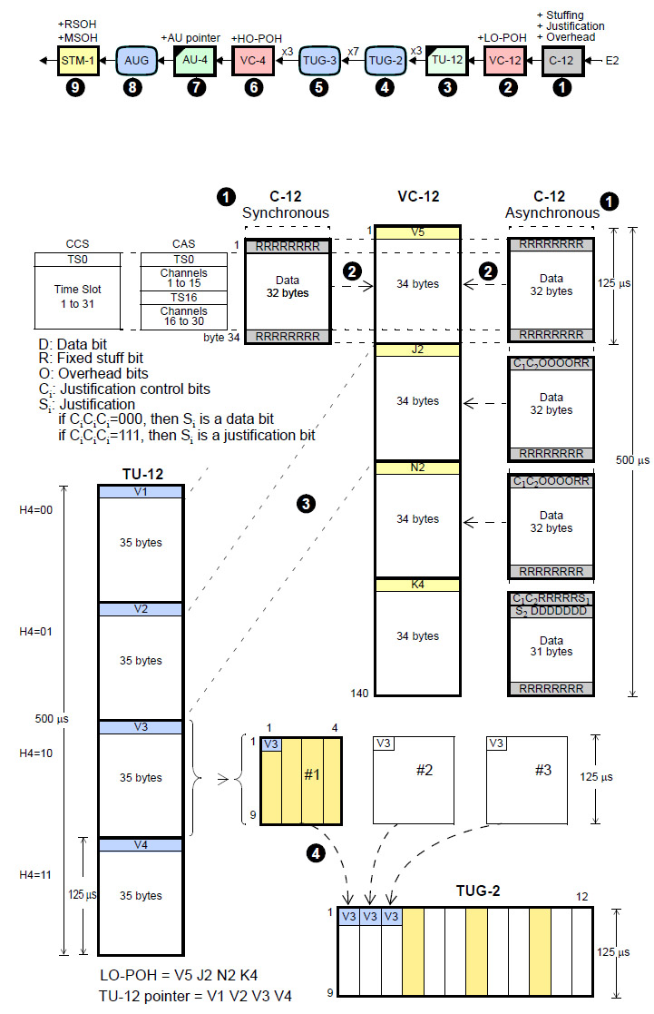
Fig 2. Synchronous and asynchronous transport of a 2-Mbit/s circuit.
Network Elements
SDH systems make use of a limited number of network elements (NEs) within which all the installations are fitted.
- Regenerators (REGs) or section terminating equipments (STEs): Every signal sent through any transmission medium (optical, electrical or radio-electrical) experiences attenuation, distortion, and noise. Regenerators supervise the received data and restore the signal’s physical characteristics, including shape and synchronization. They also manage the monitoring and maintenance functions of the regenerator section (RS) or section in SONET
- Line terminal multiplexers (LTMUX) or path terminal equipment (PTE): they are common in line and access topologies. Their function is to insert and extract data in synchronous frames (see Figure 2.10).
Add and drop multiplexers (ADMs) can insert or extract data directly into or from the traffic that is passing across them, without demultiplexing/multiplexing the frame. Direct access to the contents of the frame is a key feature of SDH, as it enables us to turn any point of the network into a service node, just by installing an ADM. - Digital cross-connects (DXCs) configure semipermanent connections to switch traffic between separate networks. The switched traffic can be either SDH streams or selected tributaries. Although it is not common, DXCs can also insert and drop tributaries in transport frames.
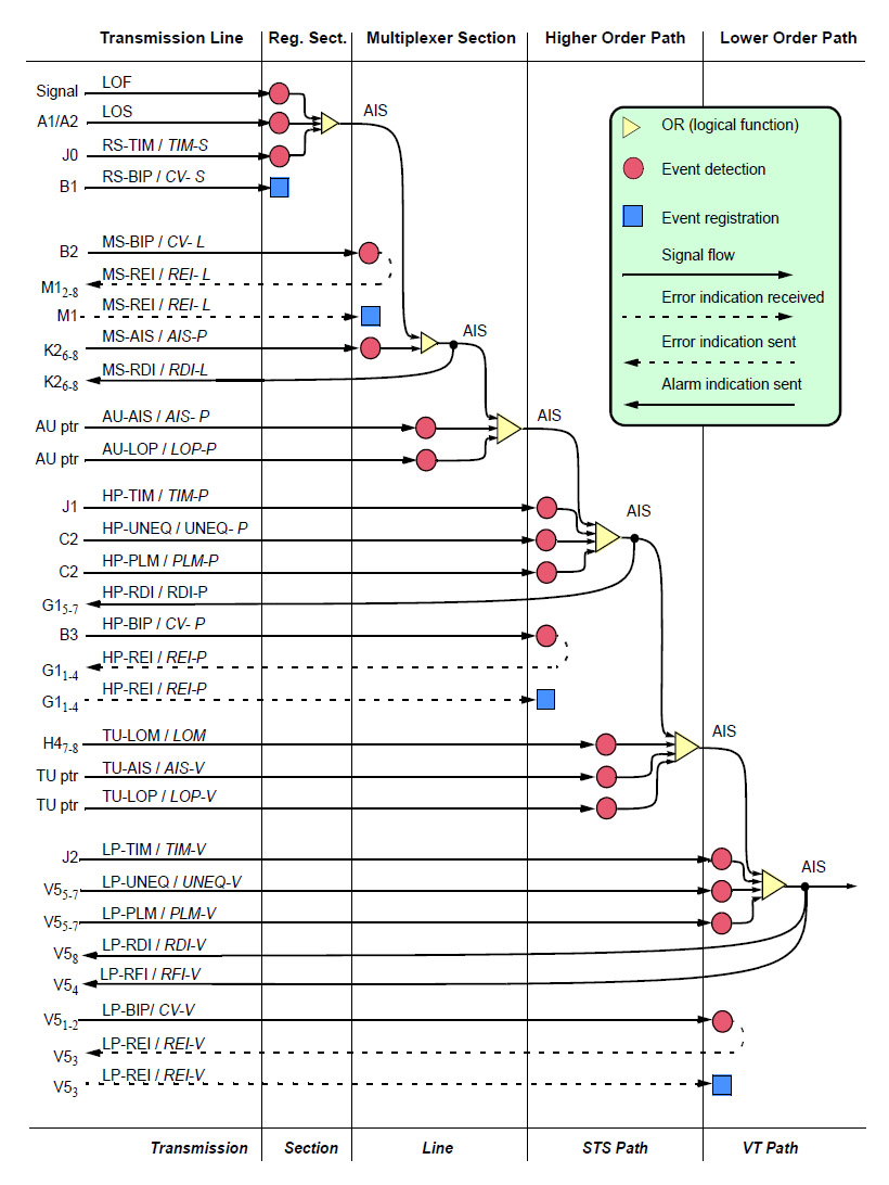
Fig 3. Events management. SDH in regular characters, SONET in italic.
SDH/SONET Layers
In plesiochronous networks, interactions are simple and direct. In synchronous networks they are more sophisticated, so responsibilities have been divided among several layers that communicate with their counterparts by making use of specific overheads, formats, and protocols. This architecture is equivalent to the layered open system interconnection (OSI) model to define and design communication networks.
Path layers
Path layers are the route to transport clients’ information across the synchronous network from its source to its destination, where the multiplexers interface with client equipment. At this layer clients’ information is mapped/demapped into a frame and path overhead is added. There are two specialized path layers:
- Lower-order path (LP), or virtual tributary path (VT Path) in SONET, to transport lower-rate services. Associated overhead is lower-order path overhead (LO-POH) or virtual tributary path overhead (VT-POH) in SONET.
- Higher-order path (HP), synchronous transport signal path (STS Path) in SONET, to transport higher-rate services or a combination of lower-rate services. Associated overhead is higher-order path overhead HO-POH or synchronous transport signal path overhead (STS-POH) in SONET.
Some of the path layer functions are routing, performance monitoring, anomalies and defect management, security and protection, as well as specific path OAM functions support.
Multiplex section or line layer
Multiplexer section (MS), or line section in SONET, is a route between two adjacent multiplexers. This layer has several capabilities such as bit error detection, and circuit protection when an intermediate link or node collapses. It also carries synchronization reference information and OAM information between nodes. Associated overhead is multiplex section overhead (MSOH) or line overhead (LOH) in SONET.
Regeneration section or section layer
The regeneration section (RS), (the section layer in SONET) is the link between two successive NEs. It reads and writes specific overheads and management functions for each type of transmission media. Its most typical functions are framing, bit error detection, and regenerator OAM functions support. Associated overhead is regeneration section overhead (RSOH) or <Default Para Font>section overhead (SOH) in SONET.
Physical layers
Fiber optics and metallic cable, together with terrestrial radio and satellite links can be used as the physical layer (PL). Fiber optics is the most common medium because of its capacity and reliability. Radio is a cost-effective medium when distance, geographical difficulties, or low-density areas make the optical alternative less practical. Nevertheless, radio has some important weaknesses; for example, noise and frequency allocation, that limit bit rates to 622 Mbps. Electrical cables are also used in some legacy installations.
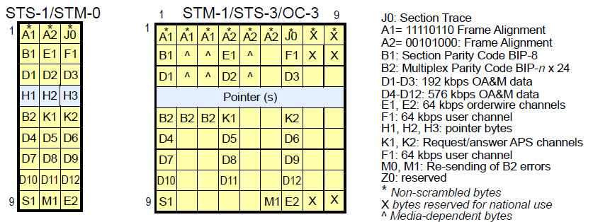
Fig 4. STM-N/OC-M frames.
SDH/SONET Frame Structure
The basic transport frame in SONET is synchronous transport signal (STS-1), while in SDH it is synchronous transmission module (STM-1) (see Figure 2.13):
- STS-1 is a 3 x 9 byte structure transmitted at 52 Mbps, which is equivalent to STM-0.
- STM-1 is a 9 x 9 byte structure transmitted at 155 Mbps, which is equivalent to optical carrier 3 (OC-3) and electrical STS-3.
Both have the same structure that is based on three types of information blocks:
- Overhead blocks: These blocks contain information that is used to manage quality, anomalies, defects, data communication channels, service channels, and so on. There are two types of overhead blocks, RSOH (managed by the regenerator section layer) and MSOH (managed by the multiplex section layer).
- Payload blocks or virtual containers (VCs): They contain a combination of client signals and overhead blocks. VC does not have a fixed position in the frame, but it floats in the frame to accommodate clock mismatches.
- Pointers: They track the VC position, pointing to its first byte, while moving inside the frame (see Figure 2.13).
Multiplexing Map
A multiplexing map is a road map that shows how to transport and multiplex a number of services in STM/OC frames.
- The client tributary (PDH, T-carrier, ATM, IP, Ethernet, etc.) needs to be mapped into a C-n container, and a POH added to form a VC-n, or a VT for SONET.
- The VC/VT is aligned with a pointer to match the transport signal rate. Pointers together with VCs form TUs or AUs.
- A multiplexing process is the next step, whereby TUG-n and AUG-n groups are created.
- When it comes to TUGs, they are multiplexed again to fill up a VC, synchronous payload envelope (SPE) in SONET, and a new alignment operation is performed.
- Finally, an administrative unit group (AUG) is placed into the STM/OC transport frame.
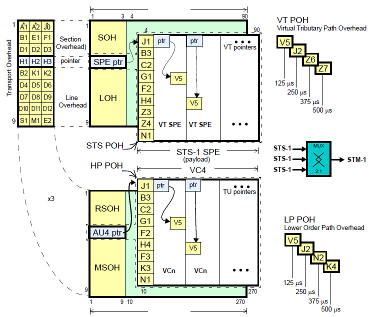
Fig 5. STS-1 and STM-1 frames.
SDH Transport Services
Today’s telecommunications services (voice, data, TV, Internet) are heterogeneous, based on a diverse combination of technologies. Most of them are clients of SDH when they need to extend their service range to wider areas.
Channelized networks in 64-Kbps circuits (POTS, ISDN, FRL, GSM, FRL) are mapped transparently in SDH synchronous containers designed to transport PDH or T-carrier tributaries. Packet technologies, such as IP, Ethernet or ATM, also have special mapping procedures.
PDH/T-carrier over SDH
To guarantee smooth migration from legacy installations, SDH standards have defined procedures to transport all legacy circuits (E1, E2, E3, E4, T1, T2, and T3).
- Synchronous mapping maintains the original 64-Kbps channel structure during the whole transmission, making it possible to access these channels directly, as bit justification is not needed. This is common in such services as ISDN or FRL, where there are nodes synchronized with the SDH reference clock. Small clock differences are adjusted with pointer movements.
- Asynchronous mapping is used when PDH and SDH do not share the same clock. Here we need bit-oriented justification to adjust any clock differences between the PDH signal and the SDH container. Due to this, the existing byte structure is lost. This scheme is rather common in POTS and in old plesiochronous circuits.
Fig 6. Synchronous and asynchronous transport of a 2-Mbps circuit.
Ethernet over SDH
Ethernet has become the standard technology for local area networks (LANs). It is cheap, easy to use, well-known, and always in constant evolution toward higher rates. Now it is also being considered as a good technology for access and metro networks, but carriers still need SDH to route high volumes of Ethernet traffic to get long haul. There are several schemes:
- Ethernet over LAPS: defined in ITU-T X.86. This is an HDLC family protocol, including performance monitoring, remote fault indication, and flow control. However, it calls for contiguous concatenated bandwidth techniques that do not match the burst nature of Ethernet.
- Generic framing procedure (GFP): defined in ITU-T Rec. G.7041. This is a protocol for mapping any type of data link service, including Ethernet, resilient packet ring (RPR), and digital video broadcasting (DVB).
- Virtual concatenation: defined in ITU-T Rec. G.707, creates right-sized pipes for the traffic, providing quite a lot of flexibility and high compatibility with legacy SDH installation techniques.
- Link capacity adjustment scheme (LCAS): defined in ITU-T Rec. G.7042. This dynamically allocates/deallocates new bandwidth to match Ethernet requirements in a flexible and efficient way. It calls for virtual concatenation.
Overheads
The key difference between SDH and its plesiochronous predecessors is in the management and monitoring capabilities SDH provides at the transmission layer. These features are based on peer protocols, standardized formats, and overhead fields. Network elements themselves generate a suitable response to management actions, reconfigurations, performance monitoring, failures, or any type of events. Overheads are also a key difference between SDH and its potential successors, based on any combination of gigabit-Ethernet (GbE), dense wavelength division multiplexed (DWDM), and IP protocols. These networks are always said to be more efficient, because they do not support most of these management facilities and, eventually, will not need overheads or protocols to support them
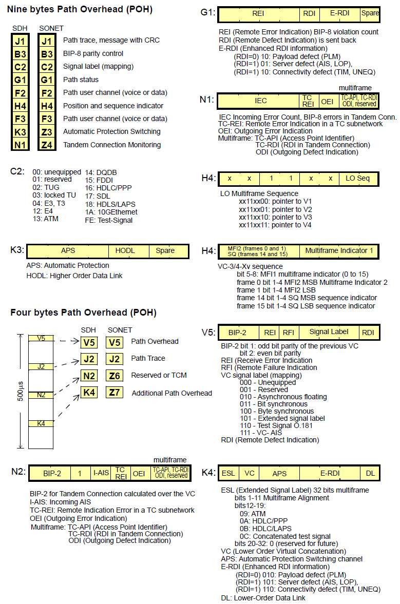
Fig 7. Four and Nine bytes Path Overhead.
The SDH/SONET Hierarchy
We have already seen the STM-1 frame, equivalent to STS-3 and OC-1 in SONET, made up of a 9 x 270 byte matrix and transmitted at 155 Mbps. The hierarchy defines higher-order frames whose bit rates are obtained by multiplying successively by four. For simplicity, each bit rate is usually referred to by its rounded-off value. The STM-n structure frame (n = 4, 16, 64, 256) consists of two section overheads (RSOH and MSOH) plus an AUG-n (see Table 2.8). Four AUG-n are block-interleaved, to create a superior structure referred to as AUG-4n. For instance, four AUG-4s are needed to create an AUG-16 (see Figure 2.27).
Like the STM-1 frame, STM-n frames are represented as a rectangular structure of 270 x n columns and 9 rows, which gives a total of 270 x n x 9 = 2,430 x n bytes. Nonetheless, the frame period remains the same as that of the STM-1 frame: 125 ms. The new SOH is therefore 3 x 9n bytes, the multiplex section 3 x 9n bytes, and 9n bytes for AU-n pointers.
When looking at the STM-n/OC-m frames, the concept of indirect multiplexing cannot be ignored. To explain this, let us look at the example of the STM-16 frame. Forming one of these frames by direct multiplexing means that it has been formed by interleaving bytes from 16 STM-1 frames. An STM-16 structure can also be obtained from four STM-4 frames, by indirect multiplexing. In this case, interleaving is carried out in blocks of 4 bytes. The resulting structure is therefore the same for both cases.
In addition to its functions outlined in previous sections, the pointer mechanism also facilitates the construction of STM-n. In effect, due to the imperfection that is inherent to synchronization, STM frames reach multiplexers with random relative alignments; that is, some of them are out of phase in respect to others. Nonetheless, the STM-n higher-order frame that leaves the multiplexer keeps its bytes grouped together in a single block. The payloads of the frames can be interleaved without prior alignment, since virtual containers will have a pointer value that has been recalculated in the overhead of the outgoing frame.
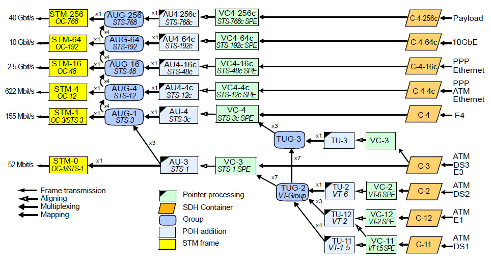
Fig 8. SDH and SONET multiplexing map.